Servicing the
Solex Carburettors
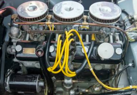
The Bristol engine in the Aceca-Bristol breathes through three downdraught Solex carburettors. Keeping them clean, correctly set and properly synchronised is the single biggest factor in how well the car runs. This is a plain-English guide, removing, dismantling, reconditioning, reassembling and tuning them, adapted from the original service instructions for these cars.
“A well-balanced set of triple Solex carburettors is the difference between a Bristol that merely runs and one that sings.”
Before you start, a note on safety
The set-up
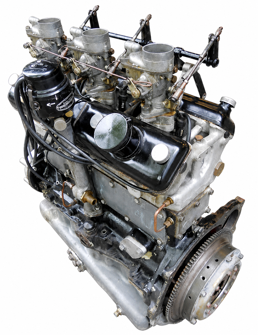
The engine is fed by three downdraught Solex carburettors, type B32 PBI-6, one per pair of cylinders, mounted on the offside of the engine and linked by a common throttle shaft. Because there are three of them working together, the golden rule of Solex tuning applies throughout: whatever you do to one carburettor, you must do equally to the other two.
Factory jet settings
These are the settings specified for this application. Individual cars, states of tune, fuel and altitude can call for changes, and some cars carry hand-annotated variations from previous owners.
| Component | Setting |
|---|---|
| Choke (venturi) | 28 |
| Main jet | 125 |
| Air correction jet | 190 |
| Pilot jet | 55 |
| Air bleed | 1.0 |
| Starter jet (petrol) | 95 |
| Starter jet (air) | 2.0 |
| Emulsion tube | 10 |
| Needle valve | 1.5 |
| Part-throttle enrichment jet | 85 |
How the carburettor works
A Solex is really several small systems sharing one body, each handling a different part of the engine's operating range. Understanding them makes both tuning and fault-finding far easier.
Dust-proofing
All the air the carburettor uses, for the float chamber, the idle circuit and the main circuit, is drawn from the same filtered source, so the fuel mixture stays balanced even as the air filter gradually clogs with use.
Cold starting, the “bi-starter”
Starting from cold is handled by a separate rotary starter device, operated by the dashboard control. In the “full rich” position it feeds a strong petrol-and-air mixture straight into the manifold, enough to fire the cold engine without over-fuelling. As the engine warms, moving the control to an intermediate position, which you can feel click home, weakens the mixture while still giving the extra volume a warming engine needs. Once warm, the control is pushed fully home and the starter is out of action. Never start a warm engine on full rich.
Idling
At idle, and just off idle, fuel metered by the pilot jet is mixed with air and delivered below the throttle. A volume-control screw sets the richness. As the throttle begins to open, extra transfer holes come into play to hand over smoothly to the main circuit, so there is no flat spot as you pull away.
Main circuit
As the throttle opens further and air speeds up through the choke, or venturi, the pressure drop draws petrol from the float chamber through the main jet. Air from the air-correction jet passes down the emulsion tube and mixes with the fuel, and this emulsified mixture is sprayed into the airstream. The air-correction jet is what keeps the mixture from going too rich as engine speed climbs.
Part-throttle enrichment
Some engines need a brief extra shot of fuel during part-throttle acceleration for a crisp response. A spring-loaded valve and diaphragm supply this through a dedicated enrichment jet, cutting it off again once the throttle is opened past a set point, so the engine then runs on the main jet alone.
Float chamber
Fuel level is held constant by a float acting on a needle valve, opening to admit petrol and closing as the correct level is reached, the reservoir that feeds all the other circuits.
See it in motion
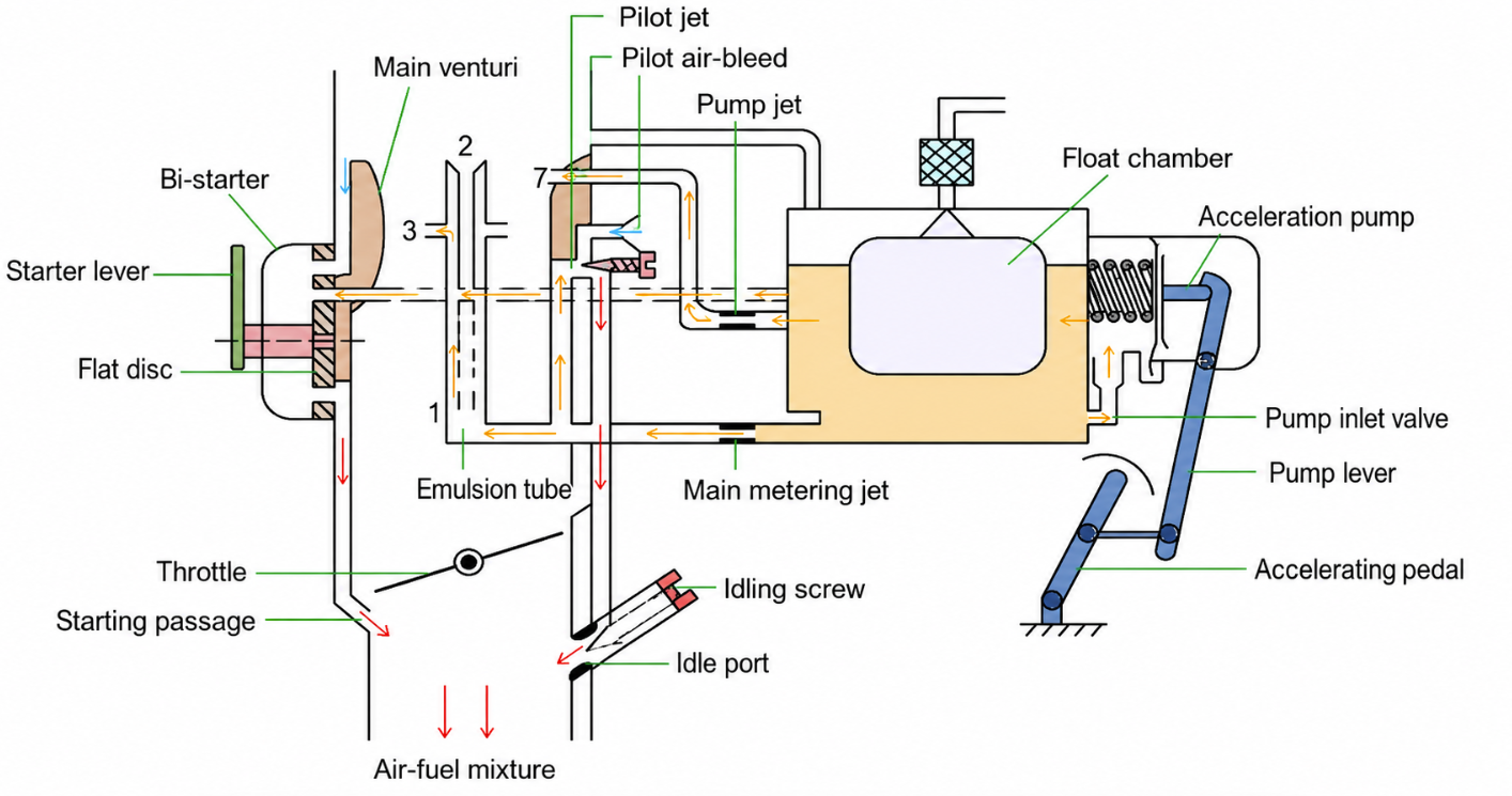
The interactive cross-section below walks through each of the Solex's fixed circuits in turn, the bi-starter rotary, the pilot circuit feeding below the throttle butterfly, the main jet drawing up through the emulsion tube at the venturi, the diaphragm-fired part-throttle enrichment shot and the float chamber that feeds them all. Use play/pause to hold a scene, slow-mo to follow the fuel and air paths more carefully, the labels toggle to reveal or hide the parts key, and the scene-jump dots to step directly to a particular circuit.
As fitted to the Aceca-Bristol's 2.0-litre straight-six, one carburettor per pair of cylinders, three linked on a common throttle shaft.
Parts key for the diagrams
| Code | Part | Code | Part |
|---|---|---|---|
| Gg | Main jet | Dd | Starter valve |
| a | Air correction jet | Gs | Starter petrol jet |
| g | Pilot jet | Ga | Starter air jet |
| s | Emulsion tube | Sl | Starter lever |
| u | Pilot air bleed | K | Choke tube (venturi) |
| Nv | Needle valve | V | Throttle butterfly |
| Mw | Main spraying well | io | Idling orifice |
| v | Reserve well | W | Idle volume screw |
| Oo | Spraying orifices | Gp | Part-throttle enrichment jet |
| Av | Float-chamber vent | Pl | Enrichment device lever |
| Dd | Starter valve | ||
| Gs | Starter petrol jet | ||
| Ga | Starter air jet | ||
| Sl | Starter lever | ||
| K | Choke tube (venturi) | ||
| V | Throttle butterfly | ||
| io | Idling orifice | ||
| W | Idle volume screw | ||
| Gp | Part-throttle enrichment jet | ||
| Pl | Enrichment device lever |
Removing the carburettors
- Loosen the clips and remove the air filters.
- Detach the petrol pipe, carefully keeping the fibre washers, gauze filters and banjo bolts safe.
- Disconnect the throttle control rods from the control shaft, keeping the nuts for reassembly.
- Disconnect the bi-starter control wire and remove the tie rod linking the carburettors.
- Ideally mark each carburettor so it goes back on the same flange. Remove the flange nuts and lift each carburettor away complete with its throttle linkage.
- Before refitting later, check that the cylinder-head and carburettor flange faces are clean and flat.
Dismantling
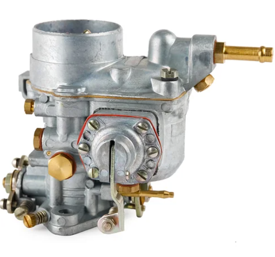
Replace all gaskets while the carburettor is apart. You need one float-chamber cover gasket and one throttle-chamber gasket per carburettor.
- Remove the float-chamber cover retaining screws and lift off the cover; remove the needle valve if required.
- Lift out the float, toggle and spindle.
- Unscrew the air-correction jet and withdraw the emulsion tube.
- Unscrew the choke, then the pilot jet, air bleed and main jet.
- Remove the bi-starter assembly, four screws, no gasket fitted.
- Separate the throttle chamber from the float chamber, four screws; lever gently if needed and discard the gasket.
- Remove the volume-control screw and spring.
- To strip the accelerator pump, note the position of the split pin on the pump control rod, then release the pump-cover screws and let the cover ease up under spring pressure before removing the pump assembly.
Reconditioning
Wash everything thoroughly. Replace worn parts, particularly worn throttle-butterfly spindles, and renew any volume-control screws with bent or scored tips. Check all mating faces for flatness; if the bi-starter brass plate face is not true, lap it lightly until it is, then wash off every trace of abrasive.
Reassembly
- Lightly oil the threads and fit the volume-control screw and spring.
- Fit the throttle chamber to the float chamber with a new gasket.
- Insert the choke with its numbered end uppermost and secure with the locating screw.
- Refit the starter jets, then the bi-starter assembly, slot to the bottom, lever facing up, no gasket.
- Refit the main jet to its holder and fit the pilot air bleed.
- Refit the pilot jet, making sure it seats fully before the head abuts the housing.
- Insert the emulsion tube into the spraying well and fit the air-correction jet above it.
- Replace the float, which only fits one way, and fit the spindle to the toggle, one side is marked “TOP”.
- Check the float-chamber fibre washer, fit the needle valve, and refit the cover with a new gasket, making sure the two dowel pegs locate correctly before tightening.
Tuning and synchronisation
This is the part that makes or breaks the car, and it is worth stating plainly: it is useless to try to synchronise three carburettors until the rest of the engine is right. The tappets must be correctly set, the contact-breaker points clean and correctly gapped, and the spark plugs clean and correctly gapped. Only then should you touch the carburettors.
Each carburettor has two external adjustments: a slow-running throttle screw and a mixture volume-control screw. To set them:
- Warm the engine fully. Switch off, and disconnect two of the three throttle control rods from the shaft so each carburettor can be set on its own.
- Working on one carburettor at a time, starting with the front: back off the slow-running screw with the throttle held closed, set a light feeler between the screw and its stop, then screw in until nipped and a further full turn from there.
- Gently screw the volume-control screw in to light contact, then back it out three-quarters of a turn. Repeat the same procedure on the other two carburettors.
- Reconnect the throttle rods, making sure all three throttles rest against their stops. Set the ignition control to retarded.
- Start the engine and adjust each slow-running screw equally until the engine idles at around 500 rpm, the original specified idle for these cars.
- Fine-tune the mixture: on each carburettor, unscrew the volume screw a quarter-turn at a time until revs just begin to drop, indicating richness, then screw back in by quarter-turns to the highest steady idle, stopping short of the point where running becomes erratic, which indicates weakness. Keep the three balanced.
- Re-check and equalise the slow-running screws to hold the target idle and keep all three in step.
The road check
With idle and balance set, test under load. Open the throttles smartly: the engine should pick up cleanly with no consistent spitting back, which is a sign of weak mixture. If it hesitates or spits, work through the mixture again, and only then consider a change of jet size. The remainder of the throttle range is best checked on the road, ideally on a familiar gradient. A main jet one size larger cures weakness at larger throttle openings; if that over-riches or over-consumes, an air-correction jet one size larger rebalances it.
Practical cautions
In normal use, leave the choke tubes and the petrol and air jets alone unless conditions genuinely differ from the British Isles or the fuel quality changes. Some fuels leave a hard, crust-like deposit in the carburettors, clean this out periodically and keep the petrol filters in good order. At altitude the mixture naturally richens; as a rough guide the standard jetting stays effective up to around 3,000 ft, after which a smaller main jet, with a corresponding change to the air-correction jet, may be needed. Some loss of power with altitude is unavoidable and cannot be tuned out.
This guide is adapted from the original service documentation for an Aceca-Bristol (chassis BEX 333) and is offered for reference. Always work safely, and consult a specialist if in doubt.

About the author
A lifelong classic-car enthusiast in North Yorkshire, near Thornton-le-Dale, who owns and maintains an AC Aceca, writing the single-model reference he always wished existed. Read the full bio.